Examples of Past Engineering Projects by R. Valdiviez

Project 11
The Conceptual Design and Dynamic Simulation of a Large Confinement Vessel for Explosive Charge Detonation Events
This engineering task covers the design and structural dynamic simulation of a large confinement vessel to be used for confining large explosive blasts that support shock physics experimentation. The vessel has an inside diameter of 10 feet, and can withstand an explosive charge detonation of up to 100 pounds of TNT, or the equivalent, and maintain the dynamic response of the components and materials within most of the design code limits defined by the American Society of Mechanical Engineers, Boiler and Pressure Vessel Code, Section VIII, Division 3 (ASME VIII‑3). The vessel will not be a code stamped vessel because at least one of the materials of construction, HSLA‑100 steel, is not a code listed pressure boundary material. Compliance with the majority of the dynamic response limits defined in ASME VIII‑3 provides a high level of confidence that the high‑hazard operation of intentionally detonating large quantities of explosives can be conducted safely within this equipment.

Project 10
The Hydraulic Simulation of a Flow Balancing Device
This engineering task involves the hydraulic simulation of a flow balancing device intended to be used in a liquid metal system where strong, pulsed magnetic fields are present. The magnetic field places a body force on the flowing liquid metal, in this case lithium, and will add hydraulic resistance to the flow circuit when the magnetic field is on. Because the magnetic field is pulsed, when the field is off the hydraulic resistance is removed, and a flow surge can develop in the flow circuit for the pump speed remaining constant. Flow surging in the circuit is not desired, so the hydraulic resistance throughout the circuit needs to be maintained at a nearly constant level. The flow balancing device, or flow balancer, is a dynamic device that is essentially timed with the magnetic field pulsing so that the balancer causes low hydraulic resistance in the circuit for the magnetic field being on, and a high hydraulic resistance, a resistance matching that of the magnetic field effect, when the magnetic field is off. The liquid metal flow circuit is intended to be maintained nominally at the design mass flow rate, will vary in an approximate 10% value band, and will thus avoid extreme flow rate changes. Extreme flow rate changes are undesirable due to the associated problems of the pump experiencing continuously changing load conditions, piping reaction forces being significantly dynamic, and flow component loads oscillating in a manner that can cause premature wear of seals and other parts.

Project 9
A Fragment Impact Simulation for A Turbomolecular Vacuum Pump Blade Failure Event
This engineering task covers the simulation of a high‑speed fragment impact into a component housing wall in order to predict if the housing material and configuration is capable of stopping the fragment. This application involves a turbine style high‑vacuum pump, known as a turbomolecular pump, that produces a high‑vacuum atmosphere within a given volume that it is connected to. The basic design of the turbomolecular pump has a motor turned rotor with several turbine blades attached to it, and which spins at high speeds, up to 60,000 revolutions per minute (rpm). The turbine blades are configured on the rotor to achieve pump stages that capture incoming gas molecules and move them axially through the stages to an eventual exhaust location. In this manner the turbomolecular pump produces a high‑vacuum environment in a molecular flow regime. In order to achieve a high molecule removal rate, or rather a high pumping speed, the rotor needs to turn at very high rotational speeds. A turbine blade failure, therefore, can throw high‑speed fragments against the turbine pump housing, and potentially breach the housing. The housing can be designed to stop the blade failure scenario’s worst‑case generated fragment without being breached. The worst‑case generated fragment can also be referred to as the design basis fragment. The design objective in this case is to keep all debris captured within the turbine pump housing, for safety reasons, as the pump rotor spins down during the blade failure event.

Project 8
The Design and Dynamic Simulation of a Support Chassis
This engineering task covers the design and structural dynamic simulation of a support chassis intended for supporting and protecting experiment diagnostic equipment that is at, or below, a weight of 1,500 pounds. The use environment of the chassis structure will place impulsive loads on the chassis. The ground motion excitation into the chassis structure is in excess of 1,000g acceleration over pulse lengths of less than 1 millisecond. The main objective of the chassis design is to mitigate the impulsive load imparted to the payload, which is the supported diagnostic equipment, to a level that can be reasonably withstood by such equipment.
Project 7
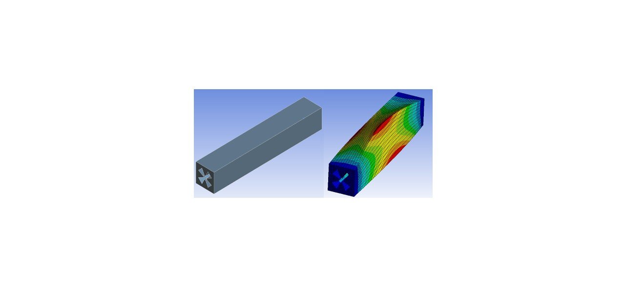
The Structural Modal Analysis of a Particle Accelerator Cavity
In this engineering task the structural modal response of a particle accelerator cavity is predicted using a simulation model. The objective of the simulation is to predict the first few response modes of the accelerator structure in order to determine if inputted residual vibration is likely, or not, to cause unacceptable motion and distortion of the accelerating cavity itself. The accelerating cavity type simulated is a radio frequency quadrupole (RFQ) structure that is an electro‑magnetic device used to start the particle acceleration process. An RFQ particle accelerator accepts low‑energy charged particles, such as protons or heavier ions, from an ion source, forms the particles into beam bunches, and increases the particle’s energy level to where the particle beam can be injected into a different, more efficient accelerating structure. Many RFQ structures are in operation in various types of facilities that utilize charged particle beams. The fundamental function served by an RFQ particle accelerator is expanding their use environment, and thus creating a need to further understand the basic structure’s fundamental dynamic response.

Project 6
The Design and Impact Simulation of a Protective Device
This engineering design task covers the design and simulation of a protective device that is required to withstand impact loading due to the common drop situation, and not sustain excessive material failure. The excessive material failure criteria in this case refers to the fact that the protective device can undergo material plastic deformation, however, it cannot experience material rupture and separation from the payload being protected.

Project 5
The Conceptual Design of a Convergent‑Divergent Flow Nozzle for Hypersonic Flow Testing
This engineering development task involves analyzing and evaluating the conceptual design of a convergent‑divergent (C‑D) flow nozzle (de Laval nozzle) in order to create a test section gas flow with a Mach number in the range of 5 to 6. The purpose of this test equipment is to provide a relatively simple flow testing capability for flow test models to be evaluated in the initial hypersonic flow regime.

project 4
The Static and Dynamic Loading Simulations of a Valve Actuator Rod
This engineering design task involves the static and dynamic simulation of a small actuator rod that is used to connect a commercial ball valve to a commercial actuator. All components are mounted on the top of a confinement vessel that is used for the detonation testing of explosive assemblies. The ball valve and coupled actuator allow for the remote venting of the vessel’s gaseous contents that are at a high static pressure following a detonation event. The valve actuator rod has static loading that it needs to withstand in order to function properly in the actuation train, and it must survive the dynamic loading of each explosive detonation event without being damaged.

project 3
The Development and Use of an RF Waveguide Set for Power Coupling
This engineering development task involves performing the mechanical development of an RF power waveguide transition set to enable the power coupling from an RF power generation and distribution system to a high‑power particle accelerator. The RF distribution system uses half‑height WR2300 waveguide, and starting at the RF window location the waveguide transitions to an internal vacuum, which is established and maintained by vacuum pumping equipment mounted on the waveguide transition set. The RF power level of one window and waveguide set is nominally 334 kW in the final configuration, with a continuous wave operation, also referred to as 100% duty factor operation. The internal design of the waveguide transition set uses a tapering geometry with a center ridge structure to accomplish the RF power coupling at the last face of the waveguide set and into the particle accelerator cavity. This tapering design with a center ridge structure, all under vacuum, creates enhanced RF power losses that are thermal power losses into the waveguide set walls. A cooling system using water is designed into each section of the waveguide set to remove the deposited thermal power, and maintain a temperature profile in the structure that allows for the proper RF coupling to occur.

project 2
The Thermal‑Hydraulic Design Analysis of a Process Heater Assembly
This engineering design task involves analyzing the thermal‑hydraulic design of a process heater assembly. The process heater assembly is made up of a rectangular duct with 28 internal electric resistance heaters. The fluid being heated flows within the duct, and over the heater bodies that are aligned longitudinally with respect to the bulk flow direction. The purpose of the heater assembly is to heat process fluids in the liquid phase having a specific gravity in the range of 0.95 to 1.1, and a specific heat value in the range of 0.98 to 1.1 Btu/lb‑F. The fluid being heated will contain no, or very low concentrations of, volatile organic compounds (VOC). The required average temperature increase for the fluid being heated is at least 100 F. The static pressure operating level of the heater assembly will be such that the fluid will remain primarily in the liquid phase at the elevated temperatures.

project 1
The Air Flow Design Through a Materials Processing Room
This engineering design task involves analyzing the ventilation air flow through a materials processing room in order to create a negative static pressure zone within the room relative to the outside ambient pressure. The negative static pressure zone for the room’s interior is desired so that materials or contaminants inside of the room will tend to be kept within the room, and not be forced out via openings and leak paths in the walls.